
Choosing CNC router feeds and speeds starts with the exact cutter, material and operation. Use the tool manufacturer’s cutting data to select an appropriate spindle speed and feed per tooth, calculate the feed rate, then verify the result on a representative test piece. A diameter-only RPM chart cannot account for every setup.
This guide covers mechanically fed CNC routing of wood and wood-based panels. It is not a parameter chart for handheld routing, aluminium, stone or every type of plastic.
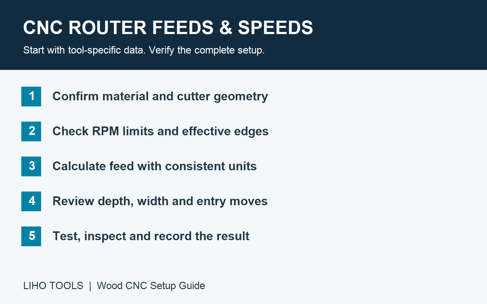
Understand the four settings before changing them
| Setting | Meaning | Why it matters |
|---|---|---|
| Spindle speed, n | Cutter rotations per minute, in RPM | Must suit the cutter and application and stay within all applicable speed limits |
| Programmed feed rate, vf | Travel speed along the cutting path | Works with RPM and effective cutting-edge count to determine nominal feed per tooth |
| Axial depth of cut, ap | Engagement along the cutter axis | Changes load and the length of edge in contact |
| Radial engagement, ae | Width of material engaged across the tool | Distinguishes full-width slotting from a light side cut |
A tool can have the same RPM and feed rate in two operations but experience very different loads because its engagement has changed.
Calculate feed rate with consistent units
For a conventional cutter with equally spaced effective cutting edges:
Feed rate = spindle speed × effective cutting edges × feed per tooth
In metric units:
vf (mm/min) = n (rev/min) × z × fz (mm/tooth)
Rearranging the equation gives:
Nominal feed per tooth = feed rate ÷ (RPM × effective cutting edges)
Do not enter metres per minute into a calculator expecting millimetres per minute. Likewise, an inch-per-tooth value needs conversion before use in a metric calculation. For ordinary spiral bits, flute count commonly supplies z; for staggered or specialised cutters, ask the supplier how many edges to use in the calculation.
Worked arithmetic example — not a cutting recommendation
Suppose a cutter’s approved application data specifies 16,000 RPM and 0.15 mm/tooth for a particular operation, and z = 2:
16,000 × 2 × 0.15 = 4,800 mm/min = 4.8 m/min
This example explains the arithmetic only. It does not recommend those inputs for a particular wood, cutter diameter, cutting depth or LIHO tool. The input values must come from suitable application data.
The calculated fz is a nominal feed per tooth. Actual chip thickness also depends on engagement and geometry; it should not be treated as a direct measurement of every chip.
Select RPM from application data, not from a maximum-speed marking
Check the cutter documentation, machine instructions and holder or collet requirements. A maximum permitted RPM is a limit, not an instruction to run at that speed. Do not exceed the lowest applicable limit, and use only a speed range suitable for the complete setup.
Diameter matters, but so do cutting geometry, tool projection, material, balance, machine capability and operation. A small straight spiral bit and a large spoilboard surfacing cutter need different application data. Increasing RPM without matching feed also reduces nominal feed per tooth.
Choose cutting depth and width together
Avoid a universal rule such as “every industrial router can cut two tool diameters deep.” Spindle power alone does not establish capacity. Rigidity, tool projection, cutting length, collet condition, chip evacuation and workholding also matter.
Full-width slotting engages a different amount of material from finishing a side wall. Check whether the supplier’s starting data assumes a particular depth and width of cut. If you change those conditions, confirm the necessary adjustments rather than transferring the same numbers automatically.
Use a supported trial cut and stay within the tool and machine instructions. When a machine cannot maintain the required cutting conditions, reconsider engagement, cutter selection or the operation as a whole.
Check entry moves separately from the main cutting feed
An acceptable contouring feed does not automatically make the same plunge or ramp safe. Confirm whether the tool supports plunging, ramping or helical entry and use the relevant angle, entry feed and clearance requirements.
There is no universal 45-degree ramp or fixed fraction of contour feed that suits every router bit. Simulate the path in CAM and check entry, lead-in and exit moves as well as the main contour.
Compression bits need the right engagement
A compression bit combines opposing cutting directions to help control the top and bottom edges of a panel. Its upcut length and transition position affect which part of the edge is cutting at the upper surface.
A shallow pass may leave the upper surface engaged by the upcut section. Check the actual tool drawing and supplier’s minimum engagement guidance. Do not add a fixed extra depth to every compression tool. If the required engagement exceeds the setup’s capability, consider a tool with a suitable shorter upcut section or a different approved strategy.
Finishing and ball-nose work need their own checks
A light finishing pass still needs to remove material effectively. Do not assume the lowest listed feed per tooth is automatically best at every stepover; radial engagement can change chip thickness. Choose the allowance and feed together with the tool supplier’s guidance.
For a ball-nose cutter, the effective diameter in contact changes with the cut geometry. Near the tip, local surface speed differs from that at the nominal diameter. A tapered ball-nose tool adds further geometry considerations. Use appropriate supplier or CAM guidance instead of copying a flat-end setup unchanged.
Record a setup that can be repeated
Before a trial, record the material and thickness, tool identification and geometry, effective cutting-edge count, RPM, feed, axial and radial engagement, entry method, projection, workholding and extraction arrangement.
Inspect edge quality, dimensions, chips and any signs of vibration or overheating. These observations are clues, not a single-cause diagnosis. Stop the spindle before inspecting or clearing the cutter. Change one variable at a time where practical, and record the result against the required finish.
For related troubleshooting, see why router bits burn wood. Plastic sheets require separate material-specific consideration; see our acrylic and polycarbonate routing guide.
For a tooling discussion, send LIHO Tools your material, machine model, tool dimensions, operation and current settings. Without those details, an apparently precise RPM or feed number can be misleading.
Technical references
- Vortex Tool: chip-load calculation and limitations of starting charts
- LMT Onsrud: production cutting tools and application-specific cutting data
- Amana Tool: router-bit safety guide
- Sandvik Coromant: milling formulas and effective cutting diameter
These references explain general principles. They do not validate settings for an unspecified LIHO tool.