PCD pre-milling before edge banding
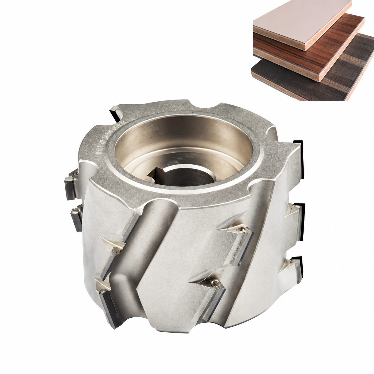
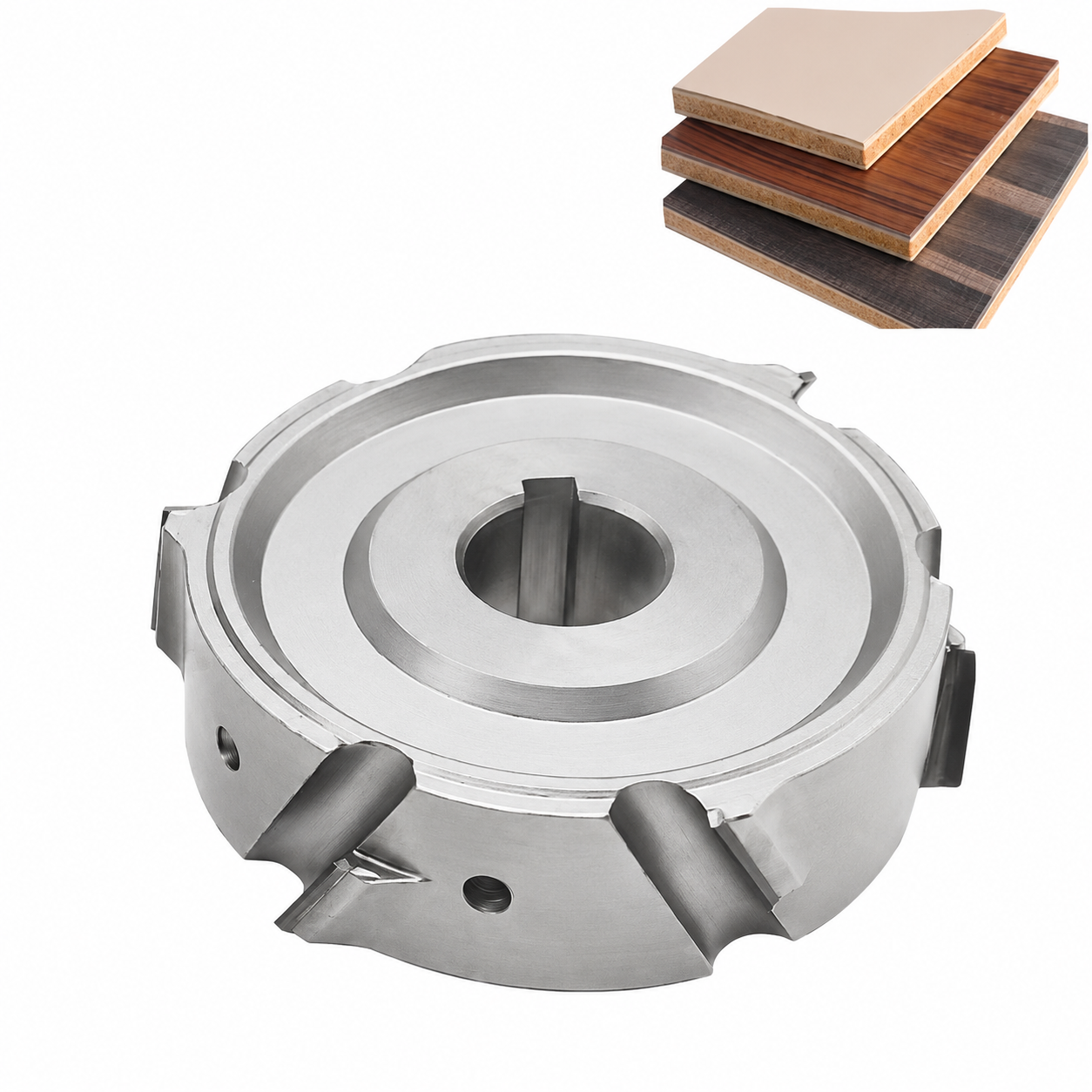
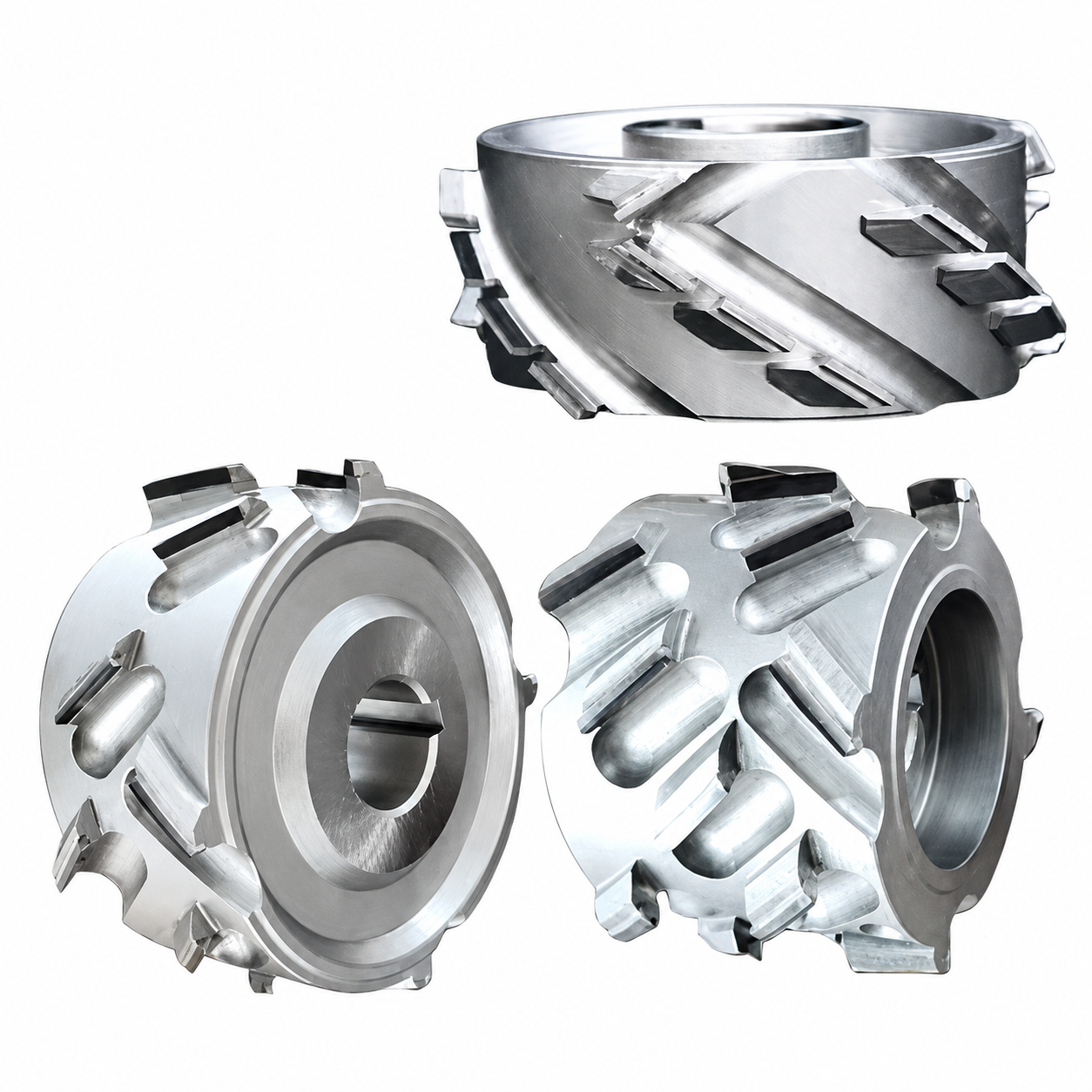
A PCD pre-milling cutter machines the panel edge before adhesive and edge band are applied. This operation removes an allowance from the edge to reduce saw marks and burrs and prepare the edge for the next process. Bond quality also depends on the board condition, adhesive and machine settings.
- Pre-milling: prepare the panel edge before the glue station.
- Gluing and edge-band application: apply adhesive and the edge band to the prepared edge.
- Trimming: remove excess edge band and machine the final edge profile after application.
Available cutter specifications
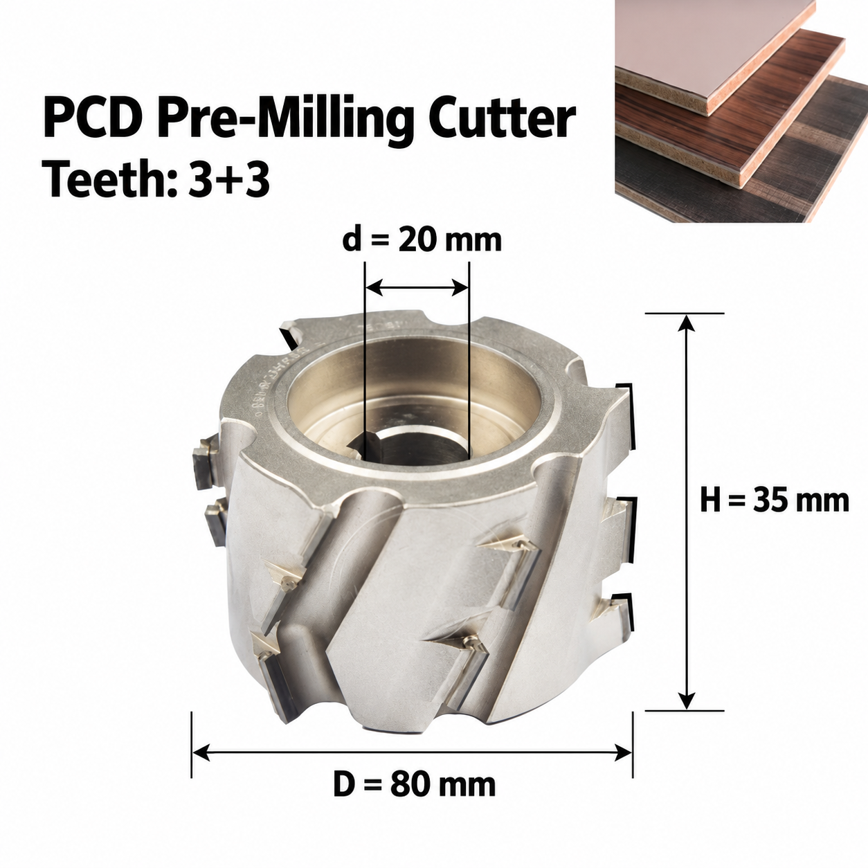
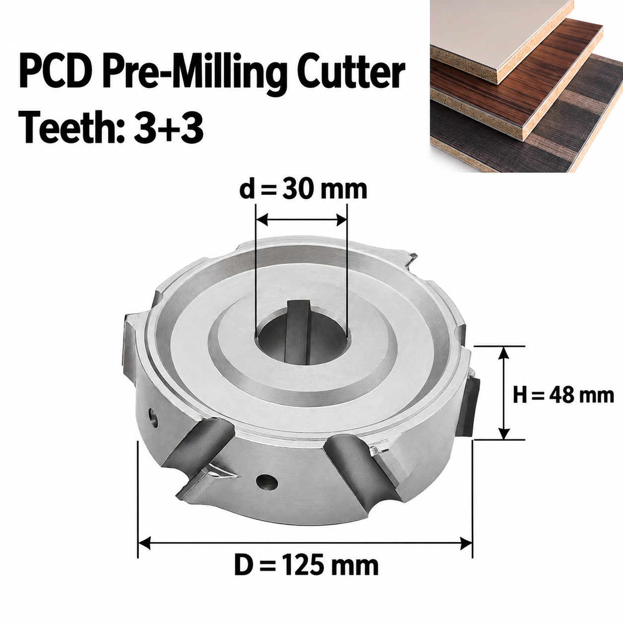
Dimensions are in millimetres. D is outside diameter, d is mounting-bore diameter and H is nominal cutter height. Each row is a listed configuration. Confirm the usable cutting height and permitted panel thickness for the actual cutter and machine; H alone is not a maximum-board-thickness specification.
| Outside diameter D (mm) | Bore d (mm) | Height H (mm) | Teeth Z | Rotation |
|---|---|---|---|---|
| 80 | 20 | 35 | 3+3 | Confirm with machine |
| 80 | 20 | 50 | 3+3 | Confirm with machine |
| 80 | 20 | 65 | 3+3 | Confirm with machine |
| 125 | 30 | 35 | 3+3 | Confirm with machine |
| 125 | 30 | 43 | 3+3 | Confirm with machine |
| 125 | 30 | 48 | 3+3 | Confirm with machine |
| 125 | 30 | 50 | 3+3 | Confirm with machine |
| 125 | 30 | 65 | 3+3 | Confirm with machine |
The dimension images show the 80 × 20 × 35 mm and 125 × 30 × 48 mm examples. The keyed bore must match the shaft and fixing arrangement. Do not combine dimensions from different rows.
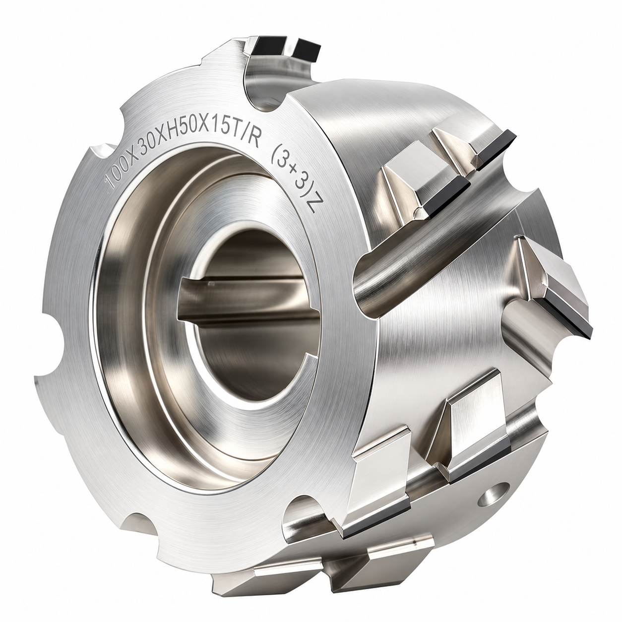
About the additional 100 mm reference photo
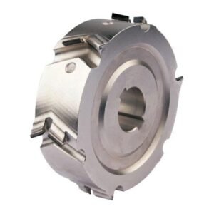
The close-up marked 100 × 30 × H50 is a separate photographed example. It is not one of the eight configurations above. Confirm its complete specification, tooth arrangement and rotation before ordering; the marking on one photographed cutter does not establish the options for the whole range.
Materials and machining application
| Material | Information needed for selection |
|---|---|
| MDF and density fibreboard | Provide board grade, thickness, coating and edge-machining allowance. |
| Calcium-silicate board | Provide the exact board composition/grade and thickness for application review. |
| Other boards or solid wood | Send the substrate or wood species and a sample/current-tool reference; suitability must be confirmed. |
The panel samples in the photographs illustrate workpiece types. They are not a guarantee that every panel grade or surface finish can be processed with every cutter configuration.
Check the machine and mounting conditions
For an edge-bander pre-milling unit, match the cutter to the actual spindle and machine configuration. For CNC spindle milling, four-sided moulding, moulding or tenoning equipment, send the operation and mounting details so suitability can be reviewed. A machine-family name alone does not establish compatibility with a particular make or model.
| Check | What to provide |
|---|---|
| Machine and operation | Manufacturer, model, pre-milling unit/spindle identification and the machining operation. |
| Cutter envelope | Current outside diameter D, bore d, nominal height H and available machine clearance. |
| Mounting bore and keyway | Photo of the bore, keyway, counterbore/recess, shaft and fixing/flange arrangement; include dimensions where available. |
| Teeth and rotation | Current tooth marking and the spindle/machine rotation marking or manufacturer diagram. Rotation is confirmed for the selected cutter. |
| Single cutter or matched pair | State whether one cutter or a matched pair is required; include each spindle position and rotation. |
| Workpiece | Board material, grade, thickness, coating and required machining allowance. |
Spindle speed, feed, maximum operating speed, rotation and machine fit must be confirmed for the supplied tool. No machine-specific operating settings are implied by this dimensional table.
Get a quote using your machine and current cutter
Send your machine make/model and current cutter D × bore d × H, plus the tooth/rotation marking, board details and a clear mounting-hole photo. For a replacement pair, photograph both cutters and their spindle positions. Include the quantity needed.
Send Machine Model & Cutter Dimensions
Prefer email? Email your dimensions and tool photos or use the contact page.
Related edge-banding tools
Compare the dedicated 80 mm edge-bander pre-milling range or the separate 100 mm edge-bander pre-milling range. For operations after edge-band application, see rough trimming cutters and fine trimming cutters. Browse all PCD edge-bander cutters.
Dimension and mounting reference images